State Machine 0.5
Bpod's state machine module can be assembled in as little as one hour at a soldering bench. Here's how.
-
Order all parts in the Bill of Materials
-
These parts can be purchased from commercial suppliers with two exceptions:
-
The printed circuit board. We have previously used JLCPCB as follows:
- Select 'Add GERBER file'. From the Bpod-CAD repository, use \PCB\BpodStateMachine\r0.5\Bpod GERBER.zip
- Select specs:
- PCB Layer: 2
- PCB Thickness: 1.6mm
- Surface Finish: Lead Free HASL
- Other default board specs are OK
- This should work out to ~$8.50 USD per board for an order of 10 boards (Oct 2023).
-
The acrylic enclosure. We have previously used Pololu's Custom laser cutting service as follows:
- Select "Request a Quote"
- Next to "My Files" click "Browse" and select C:\Bpod\CAD\Enclosure\BpodEnclosure_r0_5_X.cdr, where X is the latest version number available.
- Next to "Quantity" enter "N copies of layout provided" to order N Bpod enclosures.
- Under "Material Selection" choose "Use This Material" to the right of the line: 3.0mm (1/8") / translucent / clear matte
- Acknowledge the limitations and submit the quote request. Once the quote is provided (1-2 days), place an order for the enclosure.
-
-
-
Gather tools. You'll need:
- A clean soldering iron and sponge
- Solder
Assembly Instructions
Before assembly, ensure that you have all parts specified in the Bill of Materials in appropriate quantities. You will also need a soldering iron, solder, wire cutters, a wet soldering sponge, a small Phillips head screwdriver, and about one hour if this is your first time building a Bpod State Machine.
If you are new to soldering a circuit board with ICs, see this < 2-minute video tutorial for power-tips.
First, we will solder components into the printed circuit board.
Step 1: Add resistors, MOSFETs and status LED
Required components: - 10K resistors x 2. (BOM Part#7) - 1K resistors x 2. (BOM Part#8) - 47 ohm resistor (BOM Part#9) - MOSFET x2 (BOM Part#18) - RGB LED (BOM Part#12)
Instructions: - Solder the resistors as shown in Figure 2. - Solder the MOSFETS. Make sure the flat side matches the circuit board notation. Insert until they are nearly flush with the board. - The RGB LED has a flat corner. Align it with the corner on the board notation, or as shown in Figure 2.
The board should now appear as illustrated in Figure 2.
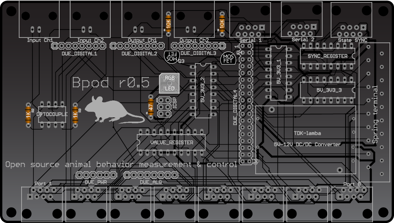
Figure 1: The board after adding resistors, MOSFETs and status LEDs
Step 2: Add integrated circuits
Required components: - SFH6732 Optical Isolator. (BOM Part#4) - TPIC6A595 Power shift register. (BOM Part#2) - CD4050BE level shifter x3 (BOM Part#5) - 74HC595N TTL shift register (BOM Part#3)
Instructions: - Solder the integrated circuits as shown in Figure 3. Make sure the notches in the ICs line up with the notches annotated on the board. - The optoisolator IC has a small circular indentation to indicate the end with the notch.
The board should now appear as illustrated in Figure 3.
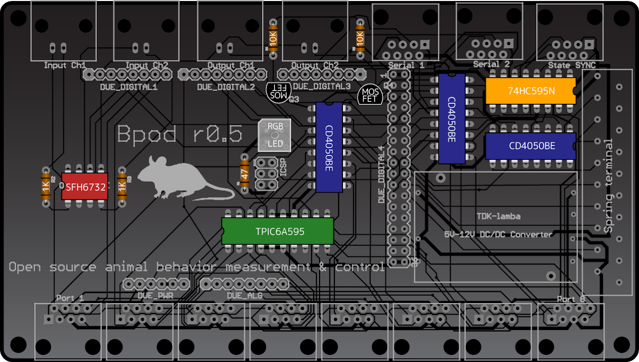
Figure 2: The board after adding ICs
Step 3: Add Arduino headers, rectangular pin headers and the TDK Lambda integrated voltage converter
Required components: - 6-pin Arduino header. (BOM Part#20) - 8-pin Arduino header x4. (BOM Part#21) - 2x36-pin male rectangular header (BOM Part#10) - 2x3 pin female rectangular header (BOM Part#11) - TDK Lambda voltage converter (BOM Part#6)
Instructions: - Solder the four 8-pin Arduino headers. They are labeled on the board: Due_Digital1, Due_Digital2, Due_Digital3 and Due_ALG. DO NOT CUT THE LEADS AFTER SOLDERING! They will be used to plug this board in to Arduino. On each header, solder one pin first, ensure the pins point straight down, then solder the others. - Solder the 6-pin Arduino header. Do not cut the leads. - Cut the 2x36-pin male header in half with a wire cutter to make a 2x18. Place the board on top of it so the silver side of the pins sticks through the board, and solder from the top as illustrated in Figure 4. - Place the board on top of the 2x3 female header, and solder from the top. - Solder the voltage converter.
The board should now appear as illustrated in Figure 4.
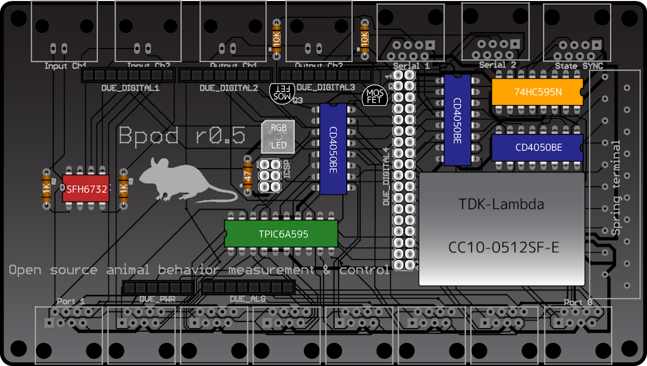
Figure 3: The board after adding headers and voltage converter
Step 4: Add Ethernet jacks, spring terminal and BNC jacks
Required components: - Ethernet jack x11. (BOM Part#13) - Spring terminal. (BOM Part#1) - BNC jack x4 (BOM Part#14)
Instructions: - Snap the Ethernet jacks into place and solder their leads. - Solder the spring terminal - Solder the BNC jacks, making sure they are resting on the board and pointing out at a 90 degree angle. This is important for the enclosure to fit.
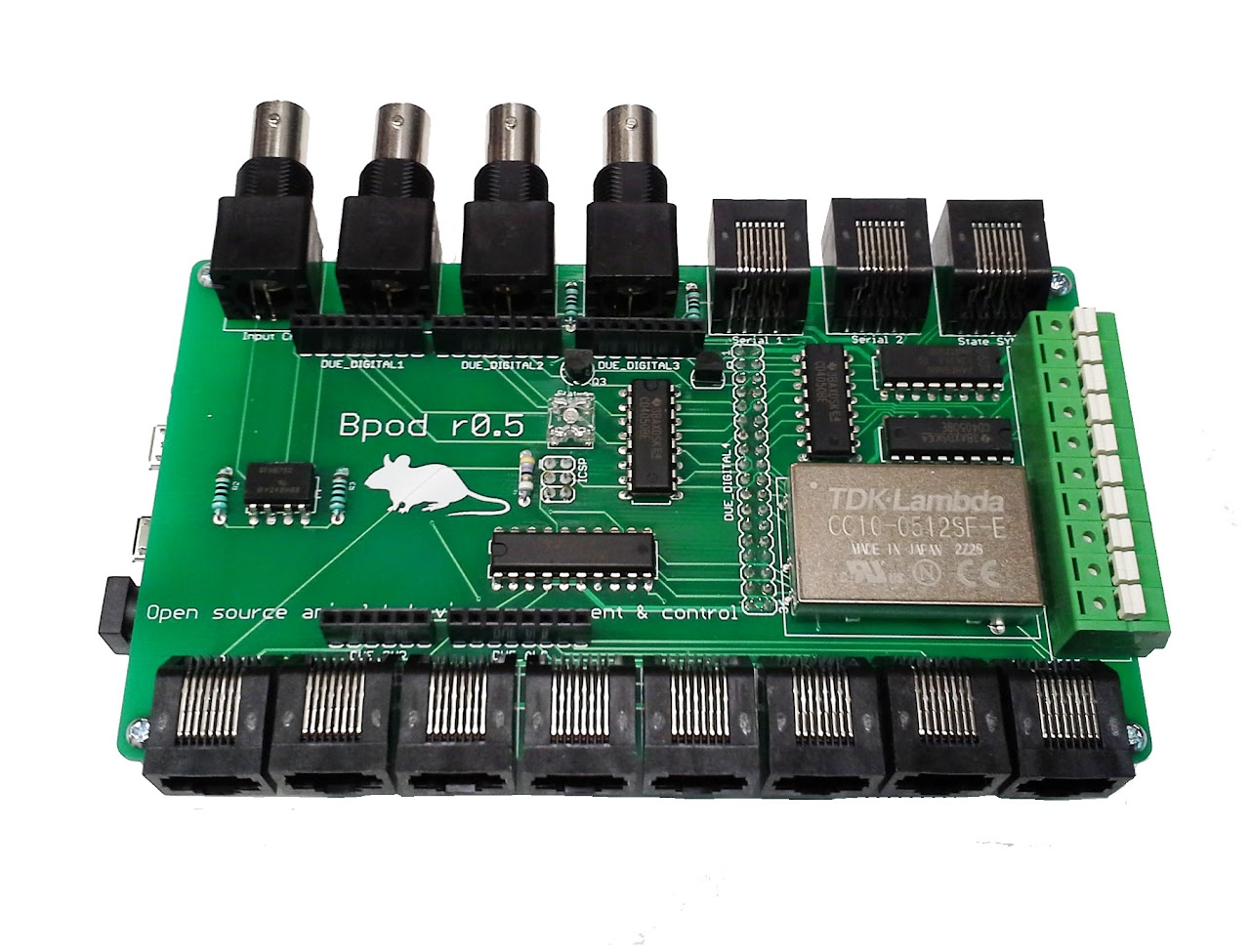
The completed board should now appear as illustrated in Figure 5.
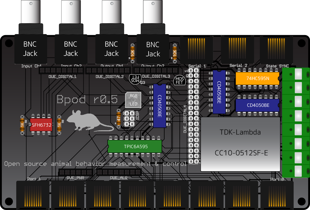
Figure 4: The completed board after adding Ethernet jacks, spring terminals and BNC jacks
Step 5: Add stand-offs and Arduino Due
Required components: - 1" 4-40 screw x4. (BOM Part#22) - 3/4" 4-40 stand-off. (BOM Part#24) - Arduino Due Microcontroller (BOM Part#25)
Instructions: - Place a screw in each corner hole, pointing down through the board. - Screw a stand-off on each corner screw until it is flush with the board. - Plug Arduino Due into the bottom of the board. The 18x2 pin header will resist - squeezing from above the header and below Arduino will help.
The completed board should now appear as shown from above: