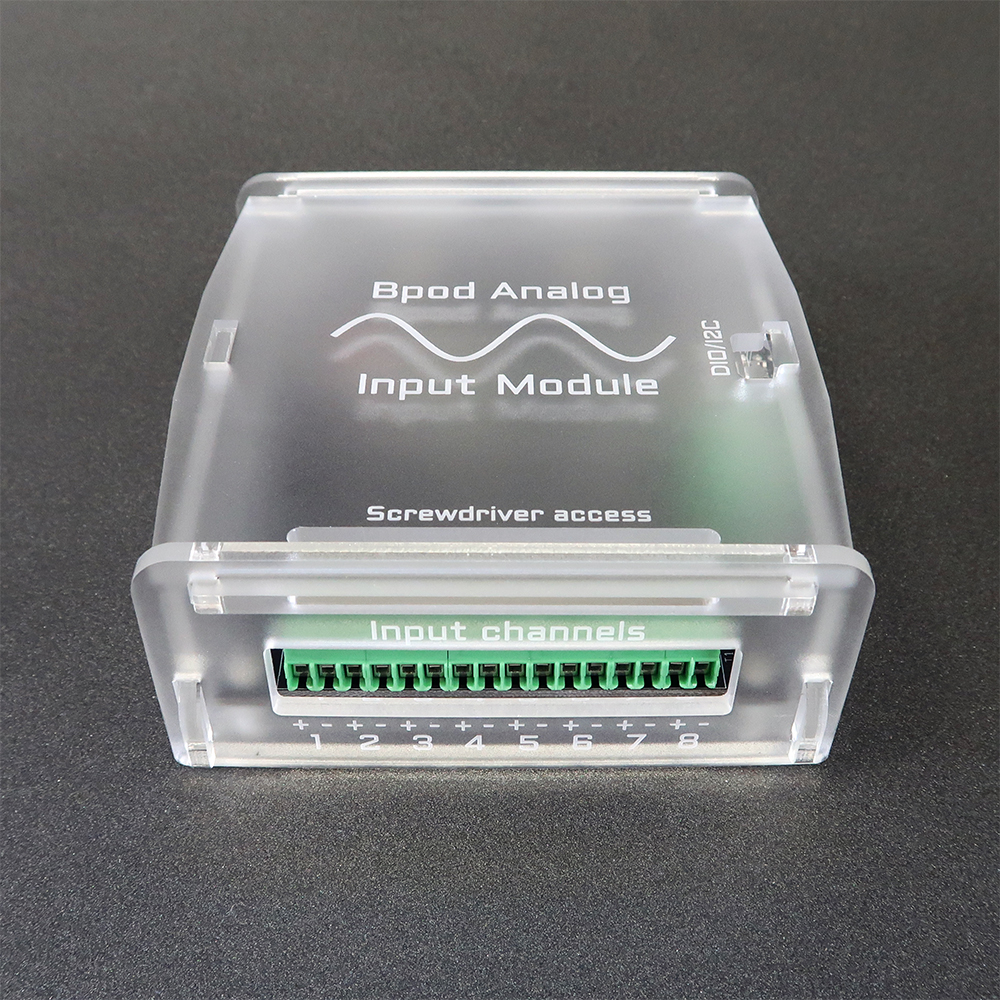
Analog Input Module
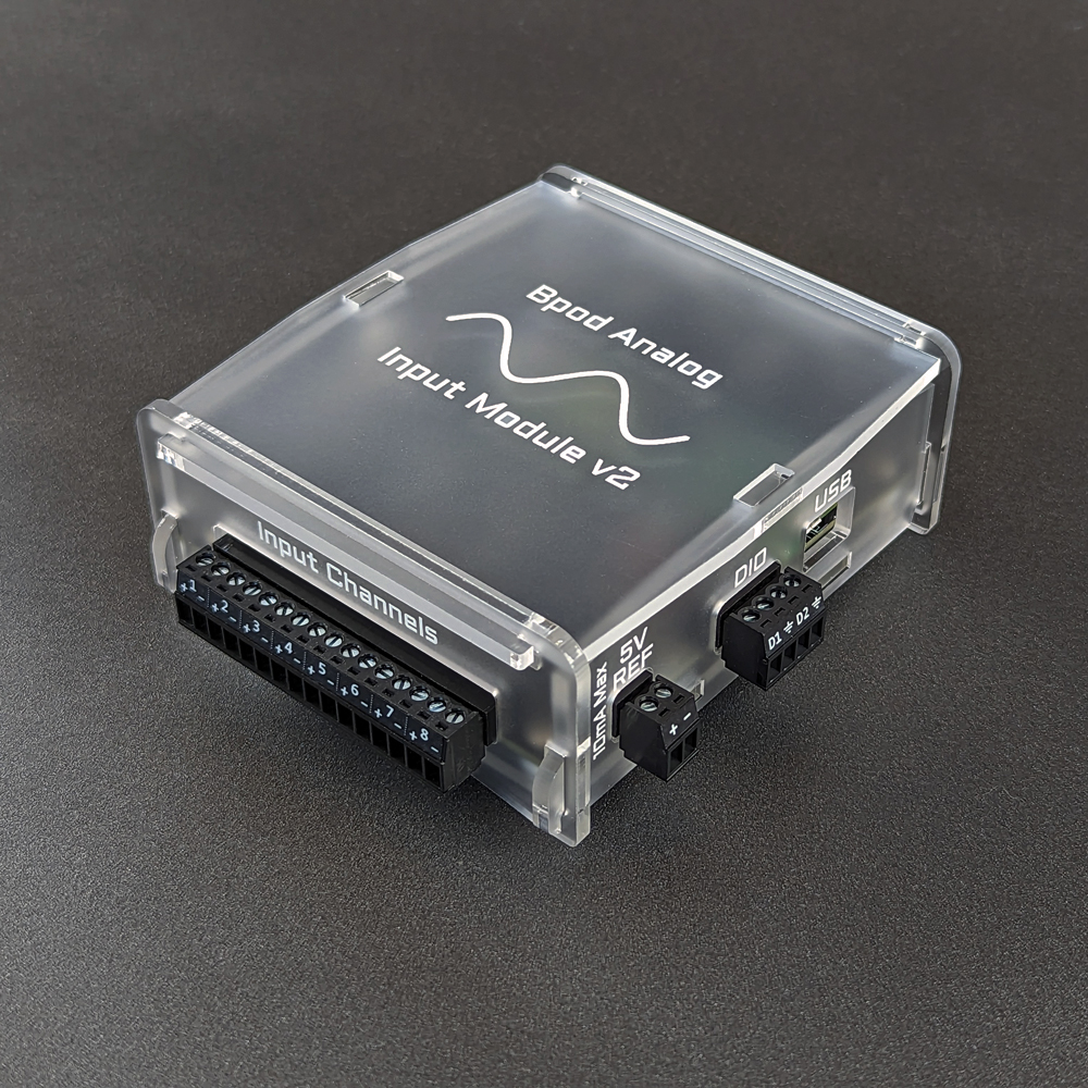
Version 2, released May 2023
Version 1, released November 2017
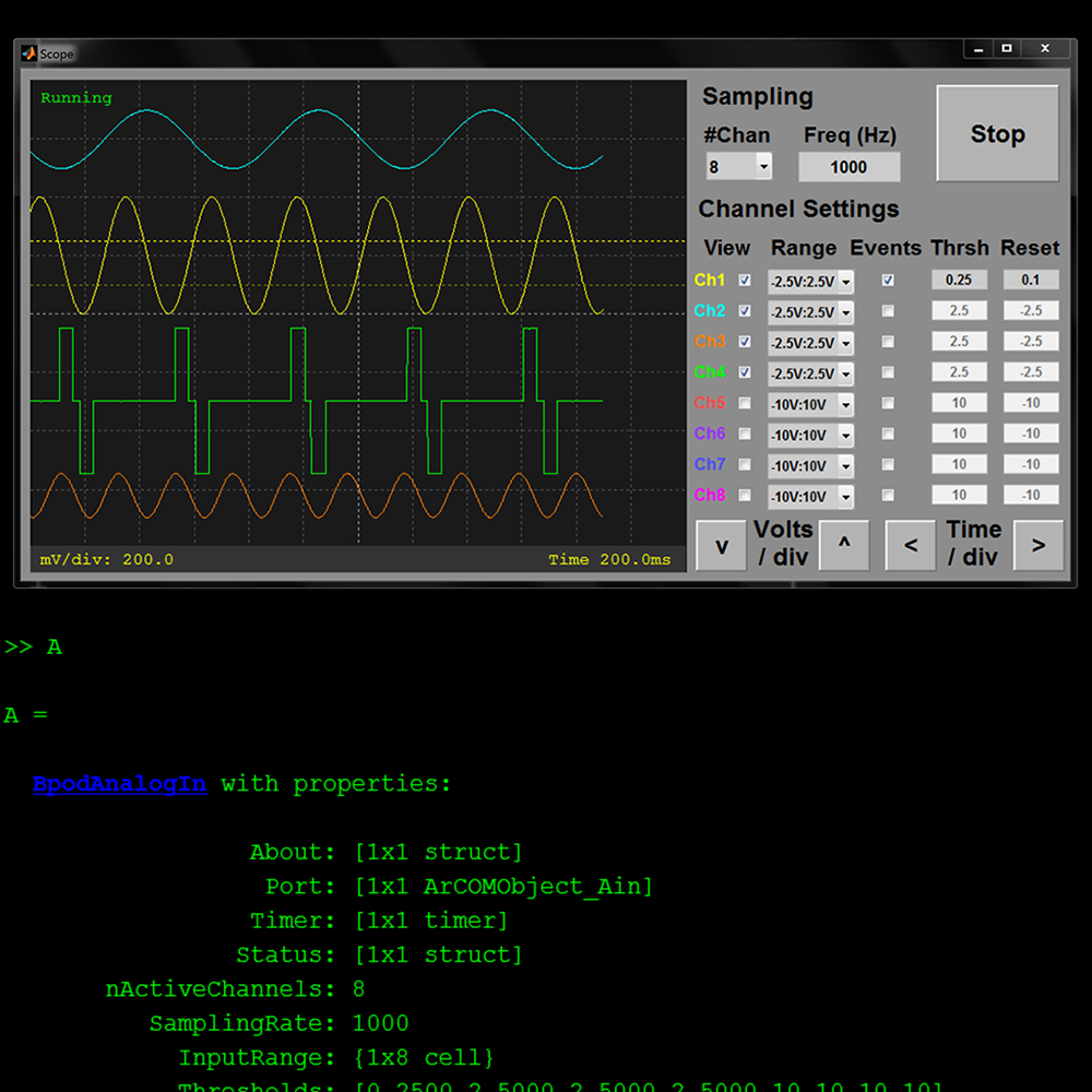
The analog input module records voltage waveforms from 8 input channels, and sends voltage threshold crossing events to the Bpod state machine.
Firmware for the analog input module is available here.
Hardware Specs (v1):
- Arduino-compatible 180MHz ARM Cortex M4 processor (Teensy 3.6)
- Integrated analog to digital (ADC) - Analog Devices AD7327
- Voltage precision: 12-bit
- 4 single-ended input range settings: -10V:10V, -5V:5V, -2.5V:2.5V, 0V:10V
- 8MB/s USB data transfer
- 16GB microSD memory for logging waveform data
- Max sampling rate: 10kHz
- Configurable voltage thresholds for generating behavior events, to control the Bpod State Machine.
- Dedicated port to stream analog data directly to the analog output module (for closed loop applications)
Hardware Specs (v2):
- Arduino-compatible 600MHz ARM Cortex M7 processor (Teensy 4.1)
- Highly integrated analog to digital (ADC) - Analog Devices AD7606C
- Voltage precision: 16-bit
- 7 single-ended input range settings: -12.5V:12.5V, -10V:10V, -6.5V:6.5V, -5V:5V, -2.5V:2.5V, 0V:5V, 0V:10V
- 8MB/s USB data transfer
- 16GB microSD memory for logging waveform data
- Max sampling rate: 50kHz
- Configurable voltage thresholds for generating behavior events, to control the Bpod State Machine.
- Dedicated port to stream analog data directly to the analog output module (for closed loop applications)
- Galvanic isolation divides analog interface from USB and MCU
- Anti-Alias filtering and oversampling on-chip
- True-differential mode selectable per-channel, w/ certain voltage ranges
- 5V reference source included to simplify connection of resistive sensors